
有手就行的ESP32-CAM监控教程
01、简介
基于esp32-cam的一个小东西。花了很多时间在网上找教程,发现基本都是使用的arduino实现的,但是使用arduino下载开发板就没成功过[流泪] [流泪];于是找到一个替代的工具 -- 简单,快捷(vscode)。
02、准备
-
开发环境安装
- 安装vscode
- vscode中安装platformio插件
-
材料
- esp32-cam开发板
- USB TO TTL 下载器
- 杜邦线一根
-
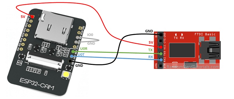
接线
03、配置项目
当platformio插件安装成功后,左侧出现一个蚂蚁头像。
- 创建项目选择 ->
AI Thinker ESP32-CAM板子; Framework ->Arduino - 下载
https://github.com/arkhipenko/esp32-cam-mjpeg开源项目 - 目录结构(修改)
- lib
- OV2640
- OV2640.cpp
- OV2640.h
- OV2640
- src
- camera_pins.h
- home_wifi_multi.h
- main.cpp
- platformio.ini
- lib
04、源代码
- OV2640.cpp
#include "OV2640.h"

#define TAG "OV2640"

// definitions appropriate for the ESP32-CAM devboard (and most clones)
camera_config_t esp32cam_config{

    .pin_pwdn = -1, // FIXME: on the TTGO T-Journal I think this is GPIO 0
    .pin_reset = 15,

    .pin_xclk = 27,

    .pin_sscb_sda = 25,
    .pin_sscb_scl = 23,

    .pin_d7 = 19,
    .pin_d6 = 36,
    .pin_d5 = 18,
    .pin_d4 = 39,
    .pin_d3 = 5,
    .pin_d2 = 34,
    .pin_d1 = 35,
    .pin_d0 = 17,
    .pin_vsync = 22,
    .pin_href = 26,
    .pin_pclk = 21,
    .xclk_freq_hz = 20000000,
    .ledc_timer = LEDC_TIMER_0,
    .ledc_channel = LEDC_CHANNEL_0,
    .pixel_format = PIXFORMAT_JPEG,
    // .frame_size = FRAMESIZE_UXGA, // needs 234K of framebuffer space
    // .frame_size = FRAMESIZE_SXGA, // needs 160K for framebuffer
    // .frame_size = FRAMESIZE_XGA, // needs 96K or even smaller FRAMESIZE_SVGA - can work if using only 1 fb
    .frame_size = FRAMESIZE_SVGA,
    .jpeg_quality = 12, //0-63 lower numbers are higher quality
    .fb_count = 2       // if more than one i2s runs in continous mode.  Use only with jpeg
};

camera_config_t esp32cam_aithinker_config{

    .pin_pwdn = 32,
    .pin_reset = -1,

    .pin_xclk = 0,

    .pin_sscb_sda = 26,
    .pin_sscb_scl = 27,

    // Note: LED GPIO is apparently 4 not sure where that goes
    // per https://github.com/donny681/ESP32_CAMERA_QR/blob/e4ef44549876457cd841f33a0892c82a71f35358/main/led.c
    .pin_d7 = 35,
    .pin_d6 = 34,
    .pin_d5 = 39,
    .pin_d4 = 36,
    .pin_d3 = 21,
    .pin_d2 = 19,
    .pin_d1 = 18,
    .pin_d0 = 5,
    .pin_vsync = 25,
    .pin_href = 23,
    .pin_pclk = 22,
    .xclk_freq_hz = 20000000,
    .ledc_timer = LEDC_TIMER_1,
    .ledc_channel = LEDC_CHANNEL_1,
    .pixel_format = PIXFORMAT_JPEG,
    // .frame_size = FRAMESIZE_UXGA, // needs 234K of framebuffer space
    // .frame_size = FRAMESIZE_SXGA, // needs 160K for framebuffer
    // .frame_size = FRAMESIZE_XGA, // needs 96K or even smaller FRAMESIZE_SVGA - can work if using only 1 fb
    .frame_size = FRAMESIZE_SVGA,
    .jpeg_quality = 12, //0-63 lower numbers are higher quality
    .fb_count = 2       // if more than one i2s runs in continous mode.  Use only with jpeg
};

camera_config_t esp32cam_ttgo_t_config{

    .pin_pwdn = 26,
    .pin_reset = -1,

    .pin_xclk = 32,

    .pin_sscb_sda = 13,
    .pin_sscb_scl = 12,

    .pin_d7 = 39,
    .pin_d6 = 36,
    .pin_d5 = 23,
    .pin_d4 = 18,
    .pin_d3 = 15,
    .pin_d2 = 4,
    .pin_d1 = 14,
    .pin_d0 = 5,
    .pin_vsync = 27,
    .pin_href = 25,
    .pin_pclk = 19,
    .xclk_freq_hz = 20000000,
    .ledc_timer = LEDC_TIMER_0,
    .ledc_channel = LEDC_CHANNEL_0,
    .pixel_format = PIXFORMAT_JPEG,
    .frame_size = FRAMESIZE_SVGA,
    .jpeg_quality = 12, //0-63 lower numbers are higher quality
    .fb_count = 2       // if more than one i2s runs in continous mode.  Use only with jpeg
};

void OV2640::run(void)
{
    if (fb)
        //return the frame buffer back to the driver for reuse
        esp_camera_fb_return(fb);

    fb = esp_camera_fb_get();
}

void OV2640::runIfNeeded(void)
{
    if (!fb)
        run();
}

int OV2640::getWidth(void)
{
    runIfNeeded();
    return fb->width;
}

int OV2640::getHeight(void)
{
    runIfNeeded();
    return fb->height;
}

size_t OV2640::getSize(void)
{
    runIfNeeded();
    if (!fb)
        return 0; // FIXME - this shouldn't be possible but apparently the new cam board returns null sometimes?
    return fb->len;
}

uint8_t *OV2640::getfb(void)
{
    runIfNeeded();
    if (!fb)
        return NULL; // FIXME - this shouldn't be possible but apparently the new cam board returns null sometimes?

    return fb->buf;
}

framesize_t OV2640::getFrameSize(void)
{
    return _cam_config.frame_size;
}

void OV2640::setFrameSize(framesize_t size)
{
    _cam_config.frame_size = size;
}

pixformat_t OV2640::getPixelFormat(void)
{
    return _cam_config.pixel_format;
}

void OV2640::setPixelFormat(pixformat_t format)
{
    switch (format)
    {
    case PIXFORMAT_RGB565:
    case PIXFORMAT_YUV422:
    case PIXFORMAT_GRAYSCALE:
    case PIXFORMAT_JPEG:
        _cam_config.pixel_format = format;
        break;
    default:
        _cam_config.pixel_format = PIXFORMAT_GRAYSCALE;
        break;
    }
}

esp_err_t OV2640::init(camera_config_t config)
{
    memset(&_cam_config, 0, sizeof(_cam_config));
    memcpy(&_cam_config, &config, sizeof(config));

    esp_err_t err = esp_camera_init(&_cam_config);
    if (err != ESP_OK)
    {
        printf("Camera probe failed with error 0x%x", err);
        return err;
    }
    // ESP_ERROR_CHECK(gpio_install_isr_service(0));

    return ESP_OK;
}
- OV2640.h
#ifndef OV2640_H_
#define OV2640_H_

#include <Arduino.h>
#include <pgmspace.h>
#include <stdio.h>
#include "esp_log.h"
#include "esp_attr.h"
#include "esp_camera.h"

extern camera_config_t esp32cam_config, esp32cam_aithinker_config, esp32cam_ttgo_t_config;

class OV2640
{
public:
    OV2640(){
        fb = NULL;
    };
    ~OV2640(){
    };
    esp_err_t init(camera_config_t config);
    void run(void);
    size_t getSize(void);
    uint8_t *getfb(void);
    int getWidth(void);
    int getHeight(void);
    framesize_t getFrameSize(void);
    pixformat_t getPixelFormat(void);

    void setFrameSize(framesize_t size);
    void setPixelFormat(pixformat_t format);

private:
    void runIfNeeded(); // grab a frame if we don't already have one

    // camera_framesize_t _frame_size;
    // camera_pixelformat_t _pixel_format;
    camera_config_t _cam_config;

    camera_fb_t *fb;
};

#endif //OV2640_H_
- camera_pins.h
#if defined(CAMERA_MODEL_WROVER_KIT)
#define PWDN_GPIO_NUM    -1
#define RESET_GPIO_NUM   -1
#define XCLK_GPIO_NUM    21
#define SIOD_GPIO_NUM    26
#define SIOC_GPIO_NUM    27

#define Y9_GPIO_NUM      35
#define Y8_GPIO_NUM      34
#define Y7_GPIO_NUM      39
#define Y6_GPIO_NUM      36
#define Y5_GPIO_NUM      19
#define Y4_GPIO_NUM      18
#define Y3_GPIO_NUM       5
#define Y2_GPIO_NUM       4
#define VSYNC_GPIO_NUM   25
#define HREF_GPIO_NUM    23
#define PCLK_GPIO_NUM    22

#elif defined(CAMERA_MODEL_ESP_EYE)
#define PWDN_GPIO_NUM    -1
#define RESET_GPIO_NUM   -1
#define XCLK_GPIO_NUM    4
#define SIOD_GPIO_NUM    18
#define SIOC_GPIO_NUM    23

#define Y9_GPIO_NUM      36
#define Y8_GPIO_NUM      37
#define Y7_GPIO_NUM      38
#define Y6_GPIO_NUM      39
#define Y5_GPIO_NUM      35
#define Y4_GPIO_NUM      14
#define Y3_GPIO_NUM      13
#define Y2_GPIO_NUM      34
#define VSYNC_GPIO_NUM   5
#define HREF_GPIO_NUM    27
#define PCLK_GPIO_NUM    25

#elif defined(CAMERA_MODEL_M5STACK_PSRAM)
#define PWDN_GPIO_NUM     -1
#define RESET_GPIO_NUM    15
#define XCLK_GPIO_NUM     27
#define SIOD_GPIO_NUM     25
#define SIOC_GPIO_NUM     23

#define Y9_GPIO_NUM       19
#define Y8_GPIO_NUM       36
#define Y7_GPIO_NUM       18
#define Y6_GPIO_NUM       39
#define Y5_GPIO_NUM        5
#define Y4_GPIO_NUM       34
#define Y3_GPIO_NUM       35
#define Y2_GPIO_NUM       32
#define VSYNC_GPIO_NUM    22
#define HREF_GPIO_NUM     26
#define PCLK_GPIO_NUM     21

#elif defined(CAMERA_MODEL_M5STACK_WIDE)
#define PWDN_GPIO_NUM     -1
#define RESET_GPIO_NUM    15
#define XCLK_GPIO_NUM     27
#define SIOD_GPIO_NUM     22
#define SIOC_GPIO_NUM     23

#define Y9_GPIO_NUM       19
#define Y8_GPIO_NUM       36
#define Y7_GPIO_NUM       18
#define Y6_GPIO_NUM       39
#define Y5_GPIO_NUM        5
#define Y4_GPIO_NUM       34
#define Y3_GPIO_NUM       35
#define Y2_GPIO_NUM       32
#define VSYNC_GPIO_NUM    25
#define HREF_GPIO_NUM     26
#define PCLK_GPIO_NUM     21

#elif defined(CAMERA_MODEL_AI_THINKER)
#define PWDN_GPIO_NUM     32
#define RESET_GPIO_NUM    -1
#define XCLK_GPIO_NUM      0
#define SIOD_GPIO_NUM     26
#define SIOC_GPIO_NUM     27

#define Y9_GPIO_NUM       35
#define Y8_GPIO_NUM       34
#define Y7_GPIO_NUM       39
#define Y6_GPIO_NUM       36
#define Y5_GPIO_NUM       21
#define Y4_GPIO_NUM       19
#define Y3_GPIO_NUM       18
#define Y2_GPIO_NUM        5
#define VSYNC_GPIO_NUM    25
#define HREF_GPIO_NUM     23
#define PCLK_GPIO_NUM     22

#else
#error "Camera model not selected"
#endif
- home_wifi_multi.h
#define SSID1 "wifi名称"
#define PWD1 "wifi密码"
- main.cpp
#include <Arduino.h>

#include "OV2640.h"
#include <WiFi.h>
#include <WebServer.h>
#include <WiFiClient.h>

// 源码: https://github.com/arkhipenko/esp32-cam-mjpeg

// Select camera model
//#define CAMERA_MODEL_WROVER_KIT
// #define CAMERA_MODEL_ESP_EYE
//#define CAMERA_MODEL_M5STACK_PSRAM
//#define CAMERA_MODEL_M5STACK_WIDE
#define CAMERA_MODEL_AI_THINKER

#include "camera_pins.h"

/*
Next one is an include with wifi credentials.
This is what you need to do:
1. Create a file called "home_wifi_multi.h" in the same folder   OR   under a separate subfolder of the "libraries" folder of Arduino IDE. (You are creating a "fake" library really - I called it "MySettings").
2. Place the following text in the file:
#define SSID1 "replace with your wifi ssid"
#define PWD1 "replace your wifi password"
3. Save.
Should work then
*/
#include "home_wifi_multi.h"

OV2640 cam;

WebServer server(80);

const char HEADER[] = "HTTP/1.1 200 OK\r\n" \
                      "Access-Control-Allow-Origin: *\r\n" \
                      "Content-Type: multipart/x-mixed-replace; boundary=123456789000000000000987654321\r\n";
const char BOUNDARY[] = "\r\n--123456789000000000000987654321\r\n";
const char CTNTTYPE[] = "Content-Type: image/jpeg\r\nContent-Length: ";
const int hdrLen = strlen(HEADER);
const int bdrLen = strlen(BOUNDARY);
const int cntLen = strlen(CTNTTYPE);

void handle_jpg_stream(void)
{
  char buf[32];
  int s;

  WiFiClient client = server.client();

  client.write(HEADER, hdrLen);
  client.write(BOUNDARY, bdrLen);

  while (true)
  {
    if (!client.connected()) break;
    cam.run();
    s = cam.getSize();
    client.write(CTNTTYPE, cntLen);
    sprintf( buf, "%d\r\n\r\n", s );
    client.write(buf, strlen(buf));
    client.write((char *)cam.getfb(), s);
    client.write(BOUNDARY, bdrLen);
  }
}

const char JHEADER[] = "HTTP/1.1 200 OK\r\n" \
                       "Content-disposition: inline; filename=capture.jpg\r\n" \
                       "Content-type: image/jpeg\r\n\r\n";
const int jhdLen = strlen(JHEADER);

void handle_jpg(void)
{
  WiFiClient client = server.client();

  if (!client.connected()) return;
  cam.run();
  client.write(JHEADER, jhdLen);
  client.write((char *)cam.getfb(), cam.getSize());
}

void handleNotFound()
{
  String message = "Server is running!\n\n";
  message += "URI: ";
  message += server.uri();
  message += "\nMethod: ";
  message += (server.method() == HTTP_GET) ? "GET" : "POST";
  message += "\nArguments: ";
  message += server.args();
  message += "\n";
  server.send(200, "text / plain", message);
}

void setup()
{

  Serial.begin(115200);
  //while (!Serial);            //wait for serial connection.

  camera_config_t config;
  config.ledc_channel = LEDC_CHANNEL_0;
  config.ledc_timer = LEDC_TIMER_0;
  config.pin_d0 = Y2_GPIO_NUM;
  config.pin_d1 = Y3_GPIO_NUM;
  config.pin_d2 = Y4_GPIO_NUM;
  config.pin_d3 = Y5_GPIO_NUM;
  config.pin_d4 = Y6_GPIO_NUM;
  config.pin_d5 = Y7_GPIO_NUM;
  config.pin_d6 = Y8_GPIO_NUM;
  config.pin_d7 = Y9_GPIO_NUM;
  config.pin_xclk = XCLK_GPIO_NUM;
  config.pin_pclk = PCLK_GPIO_NUM;
  config.pin_vsync = VSYNC_GPIO_NUM;
  config.pin_href = HREF_GPIO_NUM;
  config.pin_sscb_sda = SIOD_GPIO_NUM;
  config.pin_sscb_scl = SIOC_GPIO_NUM;
  config.pin_pwdn = PWDN_GPIO_NUM;
  config.pin_reset = RESET_GPIO_NUM;
  config.xclk_freq_hz = 20000000;
  config.pixel_format = PIXFORMAT_JPEG;

  // Frame parameters
  //  config.frame_size = FRAMESIZE_UXGA;
  config.frame_size = FRAMESIZE_QVGA;
  config.jpeg_quality = 12;
  config.fb_count = 2;

#if defined(CAMERA_MODEL_ESP_EYE)
  pinMode(13, INPUT_PULLUP);
  pinMode(14, INPUT_PULLUP);
#endif

  cam.init(config);

  IPAddress ip;

  WiFi.mode(WIFI_STA);
  WiFi.begin(SSID1, PWD1);
  while (WiFi.status() != WL_CONNECTED)
  {
    delay(500);
    Serial.print(F("."));
  }
  ip = WiFi.localIP();
  Serial.println(F("WiFi connected"));
  Serial.println("");
  Serial.println(ip);
  Serial.print("Stream Link: http://");
  Serial.print(ip);
  Serial.println("/mjpeg/1");
  server.on("/mjpeg/1", HTTP_GET, handle_jpg_stream);
  server.on("/jpg", HTTP_GET, handle_jpg);
  server.onNotFound(handleNotFound);
  server.begin();
}

void loop()
{
  server.handleClient();
}
- platformio.ini
[env:esp32cam]
platform = espressif32
board = esp32cam
framework = arduino

monitor_speed = 115200
upload_port = /dev/ttyUSB0
05、使用串口调试工具
作者的是linux系统,使用的是CuteCom 。当烧录成功后,去掉下拉线 重启开发板。串口工具界面出现链接 Stream Link: http://192.168.50.67/mjpeg/1 使用浏览器打开。
注意
PC需要与开发板连接同一wifi。非常非常重要 ---> esp32开发板在下载程序时需要下拉引脚IO0(使用杜邦线连接GND和IO0),然后再重启开发板。当运行程序时,不能下拉引脚,然后再重启开发板。