
你们好,我的网工朋友。
交换机的连接方式大家应该都知道吧,一共有三种,分别是:级联、堆叠和集群。
级联一般用来实现多台交换机之间的互相连接。
堆叠和集群,就总有网工把这两给搞迷糊了。
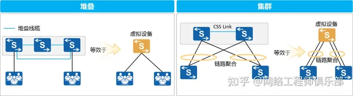
堆叠就是将多台支持堆叠特性的交换机通过堆叠线缆连接在一起,从逻辑上虚拟成一台交换设备,作为一个整体参与数据转发。
集群则是将两台支持集群特性的交换机设备组合在一起,从逻辑上虚拟成一台交换设备。
通过使用堆叠、集群技术结合链路聚合技术可以简单构建高可靠、无环的园区网络。
那具体怎么操作,今天就给你分享个经典案例,说说集群、堆叠的常用部署实施方式。
今日文章阅读福利:《思科交换机级联、堆叠、虚拟技术对比(26页)》
其实端口扩展也是在LAN网络设计中经常会碰到的问题。
目前广泛使用的扩展方式包括级连扩展、堆叠技术扩展和虚拟机框三种技术。
想搞懂这三种技术,私信我,发送暗号“堆叠”,限时获取资料。
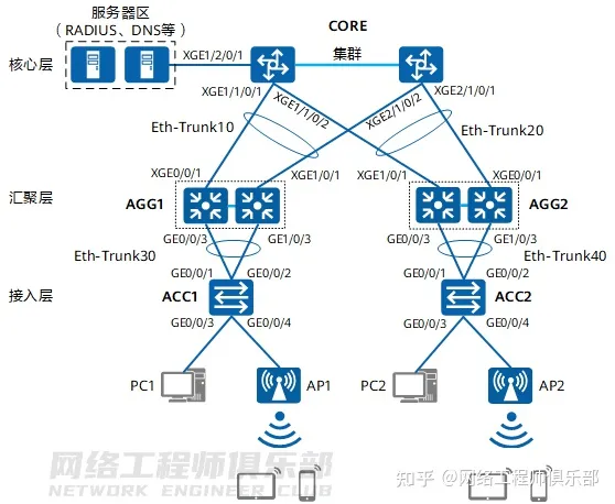
01 通用基础架构拓扑图
核心层使用两台框式交换机组建集群,汇聚层使用两台盒式交换机组建堆叠,核心层的集群与汇聚层的堆叠使用Eth-Trunk相连。
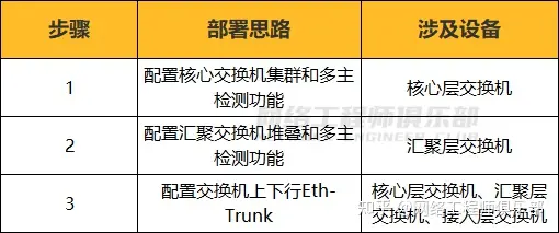
02 部署思路
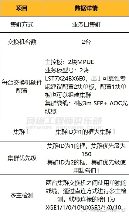
03 数据规划
集群软硬件配置规划:
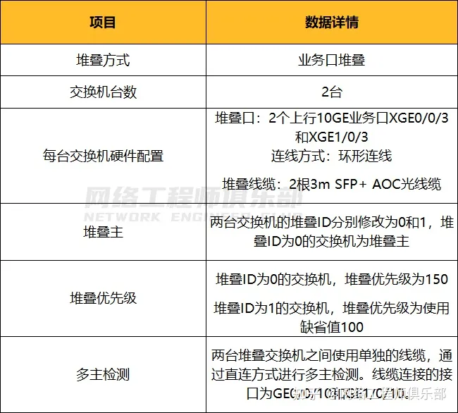
堆叠软硬件配置规划:
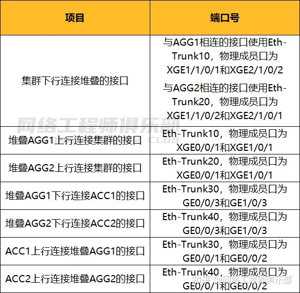
集群和堆叠接口对接规划:
04 配置步骤1:搭建集群环境
01 交换机下电,安装用于集群业务板并根据下面连线图连线集群线缆和多主检测线缆。
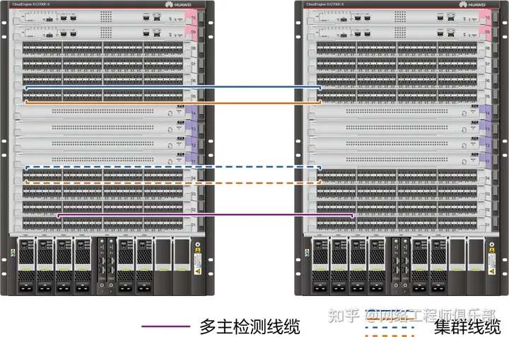
集群线缆连线图
出于可靠性考虑,推荐按照下面方式进行连线:
- 一块业务板上建议至少有两个物理成员端口加入到一个逻辑集群端口。
- 上行端口和配置多主检测的端口所在业务板建议属于非组建集群的业务板。
02 为两台交换机上电,按照数据规划分别对两台框式交换机进行配置
<HUAWEI> system-view

[HUAWEI] sysname Switch1
[Switch1] set css id 1
[Switch1] set css priority 150  //框1的集群优先级配置为150
[Switch1] interface css-port 1
[Switch1-css-port1] port interface xgigabitethernet 4/0/1 to xgigabitethernet 4/0/2 enable
[Switch1-css-port1] quit
[Switch1] interface css-port 2
[Switch1-css-port2] port interface xgigabitethernet 5/0/1 to xgigabitethernet 5/0/2 enable
[Switch1-css-port2] quit
[Switch1] display css status saved  //查看集群配置是否正确   网络工程师俱乐部
CSS port media-type: SFP+
Current Id   Saved Id     CSS Enable   CSS Mode    Priority    Master force
------------------------------------------------------------------------------
1            1            Off          LPU         150         Off

[Switch1] css enable  //集群配置确认正确后,使能集群,重启设备,为保证框ID成为主交换机,先重启Switch1
Warning: The CSS configuration will take effect only after the system is rebooted. The next CSS mode is CSS card. Reboot now? [Y/N]:y
<HUAWEI> system-view
[HUAWEI] sysname Switch2
[Switch2] set css id 2 //框2的集群优先级使用缺省值,不需要配置。网络工程师俱乐部
[Switch2] interface css-port 1
[Switch2-css-port1] port interface xgigabitethernet 4/0/1 to xgigabitethernet 4/0/2 enable
[Switch2-css-port1] quit
[Switch2] interface css-port 2
[Switch2-css-port2] port interface xgigabitethernet 5/0/1 to xgigabitethernet 5/0/2 enable
[Switch2-css-port2] quit
[Switch2] display css status saved //查看集群配置是否正确
CSS port media-type: SFP+
Current Id Saved Id CSS Enable CSS Mode Priority Master Force
------------------------------------------------------------------------------
1 2 Off LPU 1 Off
[Switch2] css enable //集群配置确认正确后,使能集群,重启设备
Warning: The CSS configuration will take effect only after the system is rebooted. The next CSS mode is CSS card. Reboot now? [Y/N]:y03 交换机重启后,查看集群是否组建成功
#通过交换机框上主控板的集群指示灯查看集群状态。
Switch1主控板上ACT灯绿色常亮,表示该主控板为集群系统主用主控板,Switch1为主交换机。
Switch2主控板上ACT灯绿色闪烁,表示该主控板为集群系统备用主控板,Switch2为备交换机。
#通过任意主控板上的Console口登录集群系统,使用命令行查看集群组建是否成功。
根据集群优先级,优先级大的Switch1会成为集群系统的主框,执行命令display device查看设备状态时,集群系统名为Switch1。
<Switch1> display device

Chassis 1 (Master Switch)
S12700E-8's Device status:
Slot  Sub Type         Online    Power      Register       Status     Role
- - - - - - - - - - - - - - - - - - - - - - - - - - - - - - - - - - - - - - -
1     -   LST7X24BX6E0 Present   PowerOn    Registered     Normal     NA
2     -   LST7X24BX6E0 Present   PowerOn    Registered     Normal     NA
3     -   -            Present   PowerOn    Unregistered   -          NA
9     -   LST7MPUE0000 Present   PowerOn    Registered     Normal     Master
10    -   LST7MPUE0000 Present   PowerOn    Registered     Normal     Slave
PWR1  -   -            Present   PowerOn    Registered     Normal     NA
CMU1  -   EH1D200CMU00 Present   PowerOn    Registered     Normal     Master
FAN1  -   -            Present   PowerOn    Registered     Normal     NA
FAN2  -   -            Present   PowerOn    Registered     Normal     NA
Chassis 2 (Standby Switch)
S12700E-8's Device status:
Slot  Sub Type         Online    Power      Register       Status     Role
- - - - - - - - - - - - - - - - - - - - - - - - - - - - - - - - - - - - - - -
1     -   LST7X24BX6E0 Present   PowerOn    Registered     Normal     NA
2     -   LST7X24BX6E0 Present   PowerOn    Registered     Normal     NA
3     -   -            Present   PowerOn    Unregistered   -          NA
9     -   LST7MPUE0000 Present   PowerOn    Registered     Normal     Master
10    -   LST7MPUE0000 Present   PowerOn    Registered     Normal     Slave
PWR1  -   -            Present   PowerOn    Registered     Normal     NA
CMU2  -   EH1D200CMU00 Present   -          Unregistered   -          NA
FAN1  -   -            Present   PowerOn    Registered     Normal     NA
FAN2  -   -            Present   PowerOn    Registered     Normal     NA
<Switch1> display css status
CSS Enable switch On
Chassis Id   CSS Enable   CSS Status      CSS Mode    Priority    Master Force
------------------------------------------------------------------------------
1            On           Master          LPU         150         Off
2            On           Standby         LPU         1           Off
<Switch1> display css channel all    //查看集群链路拓扑是否与硬件连接一致
CSS link-down-delay: 500ms

                Chassis 1               ||               Chassis 2
================================================================================
Num [CSS port]       [LPU Port]         ||    [LPU Port]            [CSS port]
 1     1/1    XGigabitEthernet1/4/0/1      XGigabitEthernet2/4/0/1      2/1
 2     1/1    XGigabitEthernet1/4/0/2      XGigabitEthernet2/4/0/2      2/1
 3     1/2    XGigabitEthernet1/5/0/1      XGigabitEthernet2/5/0/1      2/2
 4     1/2    XGigabitEthernet1/5/0/2      XGigabitEthernet2/5/0/2      2/2
                Chassis 2               ||               Chassis 1
================================================================================
Num [CSS port]       [LPU Port]         ||    [LPU Port]            [CSS port]
 1     2/1    XGigabitEthernet2/4/0/1      XGigabitEthernet1/4/0/1      1/1
 2     2/1    XGigabitEthernet2/4/0/2      XGigabitEthernet1/4/0/2      1/1
 3     2/2    XGigabitEthernet2/5/0/1      XGigabitEthernet1/5/0/1      1/2
 4     2/2    XGigabitEthernet2/5/0/2      XGigabitEthernet1/5/0/2      1/2
<Switch1> system-view
[Switch1] sysname CORE  //为便于记忆,修改集群系统的设备名
04 集群组建完成,配置多主检测
集群组建完成后,为防止集群故障分裂导致多主影响业务,在两台交换机直接连接一条线缆,用于多主检测。
线缆对应的接口分别为XGE1/1/0/10和XGE2/1/0/10,如图2-5所示。
[CORE] interface xgigabitethernet 1/1/0/10

[CORE-XGigabitEthernet1/1/0/10] mad detect mode direct
Warning: This command will block the port, and no other configuration running on this port is recommended. Continue?[Y/N]:y [CORE-XGigabitEthernet1/1/0/10] quit
[CORE] interface xgigabitethernet 2/1/0/10
[CORE-XGigabitEthernet2/1/0/10] mad detect mode direct
Warning: This command will block the port, and no other configuration running on this port is recommended. Continue?[Y/N]:y [CORE-XGigabitEthernet2/1/0/10] return
<CORE> display mad verbose   //查看多主检测配置 网络工程师俱乐部
Current MAD domain: 0
Current MAD status: Detect
Mad direct detect interfaces configured:
 XGigabitEthernet1/1/0/10
 XGigabitEthernet2/1/0/10
Mad relay detect interfaces configured:
Excluded ports(configurable):
Excluded ports(can not be configured): 网络工程师俱乐部
05 配置步骤2:搭建堆叠环境
这里以搭建堆叠AGG1为例,AGG2的搭建和配置过程与AGG1相同。
01 按照数据规划分别对两台盒式交换机进行配置
如果使用专用堆叠线缆堆叠,此步配置可以省略。
<HUAWEI> system-view

[HUAWEI] sysname Switch1
[Switch1] interface stack-port 0/1
[Switch1-stack-port0/1] port interface xgigabitethernet 0/0/3 xgigabitethernet 0/0/4 enable
Warning: Enabling stack function may cause configuration loss on the interface. Continue? [Y/N]:y
Info: This operation may take a few seconds. Please wait......
[Switch1-stack-port0/1] quit
[Switch1] stack slot 0 priority 150    //优先级设置为150,使其成为堆叠主
Warning: Do not frequently modify the priority because it will make the stack split. Continue? [Y/N]:y
[Switch1] quit
<Switch1> save  //堆叠相关的配置不需要保存,会自动写入flash。为防止其他配置丢失,这里建议执行save命令进行保存
The current configuration will be written to flash:/vrpcfg.zip.
Are you sure to continue?[Y/N]y
Now saving the current configuration to the slot 0.......
Save the configuration successfully. 网络工程师俱乐部
<HUAWEI> system-view
[HUAWEI] sysname Switch2
[Switch2] interface stack-port 0/2 //逻辑堆叠口1只能和逻辑堆叠口2相连,所以这里需要配置为逻辑堆叠口2
[Switch2-stack-port0/2] port interface xgigabitethernet 0/0/3 xgigabitethernet 0/0/4 enable
Warning: Enabling stack function may cause configuration loss on the interface. Continue? [Y/N]:y
Info: This operation may take a few seconds. Please wait......
[Switch2-stack-port0/2] quit
[Switch2] stack slot 0 renumber 1 //设置堆叠ID为1,使用缺省的堆叠优先级100
Warning: All the configurations related to the slot ID will be lost after the slot ID is modified.
Do not frequently modify the slot ID because it will make the stack split. Continue? [Y/N]:y
Info: Stack configuration has been changed, and the device needs to restart to make the configuration effective.
[Switch2] quit
<Switch2> save //堆叠相关的配置不需要保存,会自动写入flash。为防止其他配置丢失,这里建议执行save命令进行保存
The current configuration will be written to flash:/vrpcfg.zip.
Are you sure to continue?[Y/N]y
Now saving the current configuration to the slot 0.......
Save the configuration successfully.02 交换机下电,根据下面连线图连线堆叠线缆和多主检测线缆
下图使用的是S5720-56C-HI-AC设备,堆叠接口和步骤1中配置的接口保持一致。
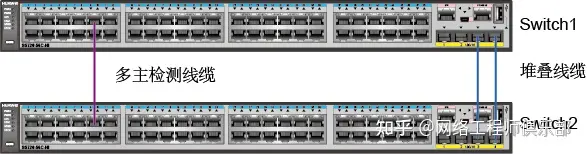
堆叠线缆连线图
03 交换机重启后,查看堆叠是否组建成功
<Switch1> display stack  //堆叠组建成功,switch1是堆叠主

Stack mode: Service-port
Stack topology type : Ring
Stack system MAC: 00e0-fc12-2355
MAC switch delay time: 10 min
Stack reserved vlan : 4093
Slot of the active management port: --
Slot     Role        Mac address      Priority   Device type
-------------------------------------------------------------
   0     Master      00e0-fc12-2355   150        S5720-56C-HI-AC
   1     Standby     00e0-fc12-2356   100        S5720-56C-HI-AC
<Switch1> system-view
[Switch1] sysname AGG1  //为便于记忆,修改堆叠系统的设备名
04 堆叠组建完成,配置多主检测
堆叠组建完成后,为防止堆叠故障分裂导致多主影响业务,在两台交换机直接连接一条线缆,用于多主检测。
线缆对应的接口分别为GE0/0/10和GE1/0/10,如上图所示。
[AGG1] interface gigabitethernet 0/0/10

[AGG1-GigabitEthernet0/0/10] mad detect mode direct
Warning: This command will block the port, and no other configuration running on this port is recommended. Continue?[Y/N]:y
[AGG1-GigabitEthernet0/0/10] quit
[AGG1] interface gigabitethernet 1/0/10
[AGG1-GigabitEtherne/1/0/10] mad detect mode direct
Warning: This command will block the port, and no other configuration running on this port is recommended. Continue?[Y/N]:y
[AGG1-GigabitEthernet1/0/10] return
<AGG1> display mad verbose   //查看多主检测配置
Current MAD domain: 0
Current MAD status: Detect
Mad direct detect interfaces configured:
 GigabitEthernet0/0/10
 GigabitEthernet1/0/10
Mad relay detect interfaces configured:
Excluded ports(configurable):
Excluded ports(can not be configured): 网络工程师俱乐部
06 配置步骤3:Eth-Trunk接口配置
配置集群和堆叠之间的Eth-Trunk接口,以及堆叠和接入层交换机之间的Eth-Trunk接口。
01 在集群上配置Eth-Trunk接口
<CORE> system-view

[CORE] interface eth-trunk 10  //创建与AGG1相连的Eth-Trunk接口
[CORE-Eth-Trunk10] mode lacp
[CORE-Eth-Trunk10] quit
[CORE] interface xgigabitethernet 1/1/0/1
[CORE-XGigabitEthernet1/1/0/1] eth-trunk 10
[CORE-XGigabitEthernet1/1/0/1] quit
[CORE] interface xgigabitethernet 2/1/0/2
[CORE-XGigabitEthernet2/1/0/2] eth-trunk 10
[CORE-XGigabitEthernet2/1/0/2] quit
[CORE] interface eth-trunk 20  //创建与AGG2相连的Eth-Trunk接口
[CORE-Eth-Trunk20] mode lacp
[CORE-Eth-Trunk20] quit
[CORE] interface xgigabitethernet 1/1/0/2
[CORE-XGigabitEthernet1/1/0/2] eth-trunk 20
[CORE-XGigabitEthernet1/1/0/2] quit
[CORE] interface xgigabitethernet 2/1/0/1
[CORE-XGigabitEthernet2/1/0/1] eth-trunk 20
[CORE-XGigabitEthernet2/1/0/1] quit
02 在堆叠AGG1上配置Eth-Trunk接口
<AGG1> system-view

[AGG1] interface eth-trunk 10  //创建与集群相连的Eth-Trunk接口
[AGG1-Eth-Trunk10] mode lacp
[AGG1-Eth-Trunk10] quit
[AGG1] interface xgigabitethernet 0/0/1
[AGG1-XGigabitEthernet0/0/1] eth-trunk 10
[AGG1-XGigabitEthernet0/0/1] quit
[AGG1] interface xgigabitethernet 1/0/1
[AGG1-XGigabitEthernet1/0/1] eth-trunk 10
[AGG1-XGigabitEthernet1/0/1] quit
[AGG1] interface eth-trunk 30  //创建与接入层交换机ACC1相连的Eth-Trunk接口
[AGG1-Eth-Trunk30] mode lacp
[AGG1-Eth-Trunk30] quit
[AGG1] interface gigabitethernet 0/0/3
[AGG1-GigabitEthernet0/0/3] eth-trunk 30
[AGG1-GigabitEthernet0/0/3] quit
[AGG1] interface gigabitethernet 1/0/3
[AGG1-GigabitEthernet1/0/3] eth-trunk 30
[AGG1-GigabitEthernet1/0/3] quit
03 在堆叠AGG2上配置Eth-Trunk接口
<AGG2> system-view

[AGG2] interface eth-trunk 20  //创建与集群相连的Eth-Trunk接口
[AGG2-Eth-Trunk20] mode lacp
[AGG2-Eth-Trunk20] quit
[AGG2] interface xgigabitethernet 0/0/1
[AGG2-XGigabitEthernet0/0/1] eth-trunk 20
[AGG2-XGigabitEthernet0/0/1] quit
[AGG2] interface xgigabitethernet 1/0/1
[AGG2-XGigabitEthernet1/0/1] eth-trunk 20
[AGG2-XGigabitEthernet1/0/1] quit
[AGG2] interface eth-trunk 40  //创建与接入层交换机ACC2相连的Eth-Trunk接口
[AGG2-Eth-Trunk40] mode lacp
[AGG2-Eth-Trunk40] quit
[AGG2] interface gigabitethernet 0/0/3
[AGG2-GigabitEthernet0/0/3] eth-trunk 40
[AGG2-GigabitEthernet0/0/3] quit
[AGG2] interface gigabitethernet 1/0/3
[AGG2-GigabitEthernet1/0/3] eth-trunk 40
[AGG2-GigabitEthernet1/0/3] quit
04 在接入层交换机ACC1上配置Eth-Trunk接口
<ACC1> system-view

[ACC1] interface eth-trunk 30  //创建与堆叠AGG1相连的Eth-Trunk接口
[ACC1-Eth-Trunk30] mode lacp
[ACC1-Eth-Trunk30] quit
[ACC1] interface gigabitethernet 0/0/1
[ACC1-GigabitEthernet0/0/1] eth-trunk 30
[ACC1-GigabitEthernet0/0/1] quit
[ACC1] interface gigabitethernet 0/0/2
[ACC1-GigabitEthernet0/0/2] eth-trunk 30
[ACC1-GigabitEthernet0/0/2] quit
05 在接入层交换机ACC2上配置Eth-Trunk接口
<ACC2> system-view

[ACC2] interface eth-trunk 40  //创建与堆叠AGG2相连的Eth-Trunk接口
[ACC2-Eth-Trunk40] mode lacp
[ACC2-Eth-Trunk40] quit
[ACC2] interface gigabitethernet 0/0/1
[ACC2-GigabitEthernet0/0/1] eth-trunk 40
[ACC2-GigabitEthernet0/0/1] quit
[ACC2] interface gigabitethernet 0/0/2
[ACC2-GigabitEthernet0/0/2] eth-trunk 40
[ACC2-GigabitEthernet0/0/2] quit
整理:老杨丨10年资深网络工程师,更多网工提升干货,请关注公众号:网络工程师俱乐部